

Projection Method
TrueGrid® 's unique projection method takes the menial tasks out of capturing geometric features in a mesh and consistently conforms the mesh to any geometry. Coupled with the multi-block approach, TrueGrid® can deal with complex geometries modeling objects such as turbines, pumps, jet engines, wings, and transmissions, drastically reducing the time involved by using the projection method.
The projection method is a collection of techniques used to place nodes of the mesh onto surfaces. Surface imperfections are ignored, and intersections of surfaces are automatically located. Most importantly, the surfaces do not have to meet perfectly for the projection method to work. The geometry can even be built using familiar computer programs such as Pro/ENGINEER®. It may not be desirable or feasible for a user to build any or all of the geometry with a solids modeler or a CAD/CAM system, and for this reason we have included a powerful set of 2D and 3D geometry tools in TrueGrid®.
The Projection Method is Easy
Surfaces and Interpolation
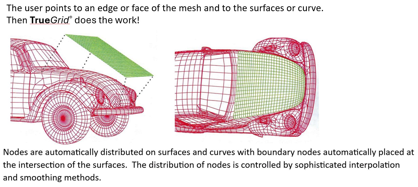
TrueGrid® takes a mesh which crudely approximates a given object and automatically adjusts it so that it exactly matches the object. This is done efficiently and accurately for all surfaces. The boundaries of surfaces require no special care; surfaces can have holes or overlap with no complications. TrueGrid® will smooth these surfaces by approximating the tangent plane.
Surface intersections are critical for TrueGrid® since the majority of the computations are spent in properly distributing edge nodes along the intersection of two surfaces. This is done by projecting each interpolated edge point to both surfaces. The resulting tangent planes are intersected to form a local approximate intersection of the two surfaces. The node is subsequently moved toward this intersection and the process is repeated until it converges. Any number of surfaces of all types can be combined to form a complex surface. Complex surfaces can be used in the projection method.
The projection method can be simplified into three steps making this Intersecting Pipes example easy.
| Step 1: Define the geometry, import the geometry from a CAD/CAM system or Solids Modeler, or import a set of polygons. Step 2: Use rectangular blocks to construct a crude approximation of the mesh. TrueGrid® makes this easy. Step 3: Project to the appropriate surfaces. Edges required to be on two surfaces are automatically projected to the intersection of the two surfaces. |
