

Pre-Processing
TrueGrid® is compatible with today's most popular simulation codes including Abaqus, ANSYS, LS-Dyna and NASTRAN (see below for a complete list). Beyond generating the mesh for these simulation codes, TrueGrid® has extensive pre-processing features as well. TrueGrid® generates control parameters, options, loads, contact surfaces, and conditions. Element type, section, and material properties can also be specified.
The TrueGrid® mesh generation process goes through multiple phases controlled by the user. Initially TrueGrid® reads in the geometry from a CAD/CAM IGES file; or you can define it directly in TrueGrid®. Parts are individually defined and refined through multiple iterations. You define the part by assigning element and material properties, loads and conditions, sets, constraints and boundaries, and diagnostics. The mesh is then defined for this part by performing geometric and topological operations. Diagnostic tools make it easy to measure the quality of the mesh. Then you can make local or global changes to the mesh to improve its quality.
TrueGrid® merges the parts into a model. Models can be made up of identical parts that can be replicated any number of times and glued together. Other models may be made up of dissimilar parts. Then the mesh element counts don't match for glueing the parts together. But that’s OK! TrueGrid®'s unique transitional element algorithm will automatically transition hexahedral, or quadrilateral meshes across interfaces using only hexahedral or quadrilateral elements, respectively. At any time, the complete model including surfaces, curves, parts, diagnostics, materials, conditions, loads, and constraints can be displayed.
Listed here are the supported simulation codes:
| TASCflow ABAQUS ANSYS DYNA3D CFX5 NEUTRAL FILE FLUENT CFD-ACE | FIDAP GILA GRIDGEN3 NASTRAN NIKE3D SAMI TOPAZ3D KIVA | ALE3D PLOT3D STARCD CF3D GEMINI NE/NASTRAN MARC | CFX4 ES3D GILA EXODUS II LS-DYNA3D AUTODYN |
Element and Material Properties
Most simulation codes have a set of properties associated with each material part. In TrueGrid® you can select these material part properties and the associated element types. Then assign a material model to elements. This can be done by either selecting a region in the part phase or by assigning the material model to an element set.
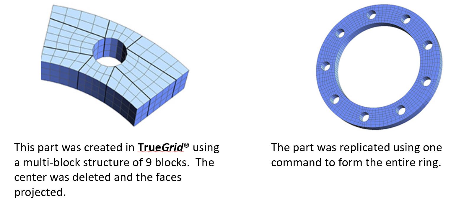
Part Replication
Transitions and Assemblies
The transitional block boundary command is a command for gluing parts with dissimilar element counts. TrueGrid® can automatically transition hexahedral or quadrilateral meshes across block boundary interfaces using only hexahedral or quadrilateral elements, respectively. TrueGrid® automatically replaces a row of hex (or quad shell) elements at the interface with a row that sews the two parts together to produce a node for node, edge for edge, and face for face matching across the interface.
The block boundary feature ensures exact interfacing between parts. Transitioning between dissimilar parts is automatic and guarantees the same block boundary precision. With this feature, you can easily replicate parts to form complex assemblies from simple components. The include feature can be invoked to re-use template parts.
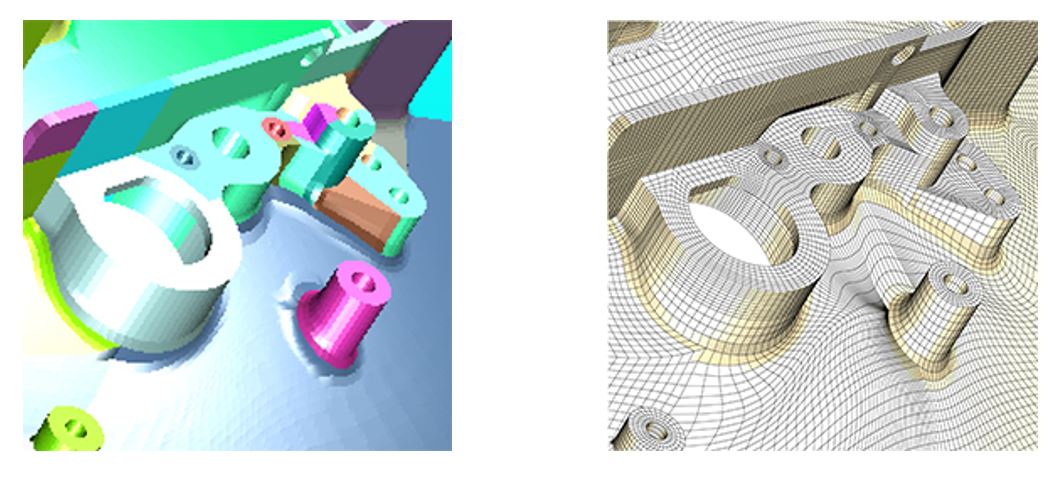
In this example a complex model is broken into 177 parts and glued together. Each color represents a different part.
Zooming in on the mesh, you can see that the parts match perfectly.
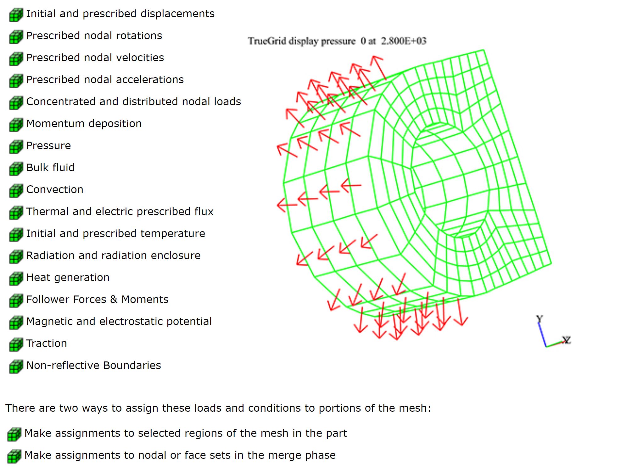
Loads and Conditions
Loads and conditions can be assigned to various parts of the model.
This include:
Diagnostics
TrueGrid® sends out warning and error messages when there are syntactic errors, omissions in the component definitions, or incompatibilities in the geometry. For example, it knows when it is asked to intersect surfaces which are tangent or otherwise do not intersect. In some cases, it applies obvious fixes such as extending the boundary of a surface by a small amount along the tangent plane to make an intersection. In other cases, TrueGrid® gives the user a detailed warning message. In all cases, TrueGrid® makes reasonable assumptions.
The merging of parts into one model serves as a diagnostic since, occasionally, the process of merging parts into a single model will reveal problems which could not be detected by looking at the parts separately. A report is issued for each merger, listing the number of nodes merged between each pair of parts. Furthermore, the merging process can be combined with the diagnostics graphics, to detect problems in the design of the mesh. After merging, the corresponding merged nodes are plotted as one node. Nodes that have been merged can be highlighted in the picture. The highlighted nodes could be nodes merged between any two parts, between a part and the rest of the models, or all merged nodes.
The graphics is probably the single most important diagnostics feature of any mesh generator. In addition to the usual manipulation of the mesh for viewing, TrueGrid® lets you add tokens to the picture representing a wide range of conditions. For example, the local interior coordinate axis of each element can be color coded. This can be important when using an anisotropic material model where all element local coordinate systems must be properly aligned.
Commands are available to calculate the volume, mass, center of gravity, momentum, moments of inertia, and products of inertia for all parts and materials of the model or any subset thereof. Here are just some of the tests you can run and diagnostics you can get:
- The volume of each block element
- An absolute volume test
- One point volume integration test
- A Jacobian test for each element
- An orthogonality test applied to the mesh
- The smallest dimension of each element
- An aspect ratio test
The notion of a good mesh is relative. In some applications, orthogonality is all you need. In other applications, it is a combination of orthogonality and size of elements. In most cases, the criteria for goodness cannot be strictly imposed on the mesh since this would be an over-specification of the mesh problem. In other words, you will always have to make compromises affecting mesh quality. To help you make good compromises, TrueGrid® offers several measures of the mesh, so you can test for different types of goodness in the mesh. These tests should be combined with other heuristics, depending on your application.
