
TrueGrid® CFD Gallery
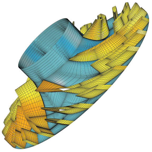
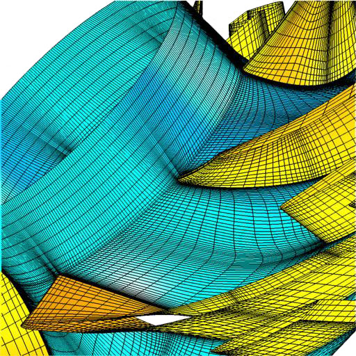
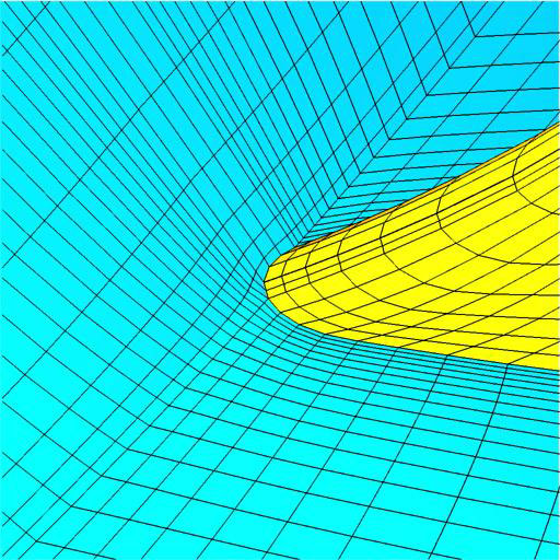
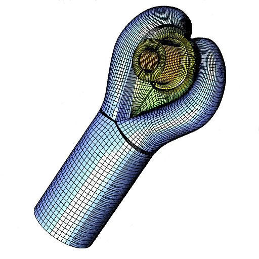
Mesh of an Impeller
The geometry for this model was 10 digital flow paths across each blade. Starting with this geometry, it took 4 hours to build this mesh using TrueGrid®. This mesh is for visualization of the fluid boundaries. Usually a periodic portion is simulated.
 |
 |
 |
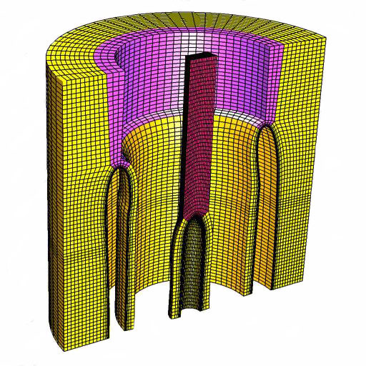
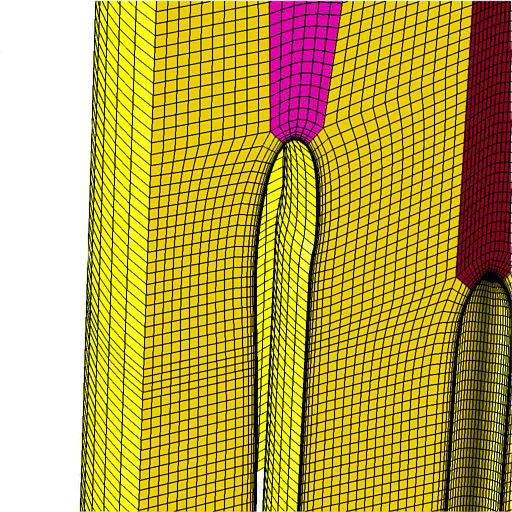
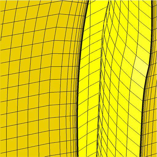
Hexahedral Mesh of Aluminum Flow About a Die
This all hex mesh was designed from a solids model. Aluminum is forced from the back of the model, as you view this picture. The holes in the mesh are for the braces of the die. The aluminum extrudes as a thin walled pipe with a planar section down the middle.
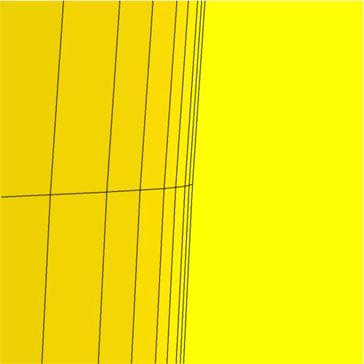
CFD Model of an Inlet to a Centrifugal Compressor
Containing 200,000 nearly orthogonal hexahedral elements, this model was constructed with a multiple block butterfly configuration. Some of the geometry was imported and some built within TrueGrid®. Small elements in the boundary areas were required by the CFD code. A splitter vane in the middle is carefully meshed.
CFD Grid of the Air About an Engine Nacelle
The thickness of the nearly orthogonal boundary elements in this model is one millionth of the radius of the nacelle. Half of the model is shown with some of the mesh removed to see inside. A template is used to build this, so that the mesh generation is essentially automatic. The fluid for the geometry (and magnification of the boundary layer) and the CAD model are shown below.
 |
 |
 |
 |
 |
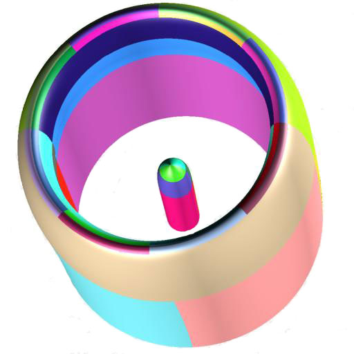 |
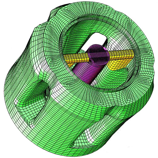
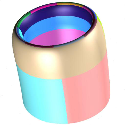
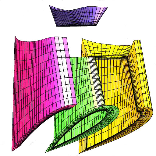
CFD Grid of the Water About a Submarine Tail Fin
This is an exploded view of the three block meshes of water that encase a submarine tail fin (the green mesh). The boundary layer of the very thin orthogonal elements are confined to the area of the tail fin. Notice how the boundary layer mesh lines wrap around the tail fin, so that no part of the boundary layer is noticeable outside of the three blocks.
CFD Model of the Fluid in a Volute for a Centrifugal Compressor
The area of the cross section of the volute grows linearly with respect to rotation around the volute. Each cross section is a five block butterfly. A splitter vane region, which separates the two regions of the volute where it crosses itself, is highly resolved to capture the curvature and fluid action. The geometry is in the form of a set of 2D spline knot points every 15 degrees. This is easily meshed with TrueGrid®.
