
Transitions and Assemblies
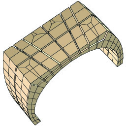
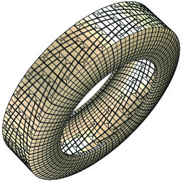
Two parts can be glued together using the block boundary feature. This assures that the coincident nodes in the two parts are identical and there is a 1:1 correspondence on both sides. This makes it easier to build complex models by first building each component and then gluing the components together. Alternatively, two regions in the same part can be glued together. Transformations can be applied to one side of the gluing so that it can be used to form periodic replications. In the example below, simple components with perodic block boundaries produced the treads on a model of a tire.
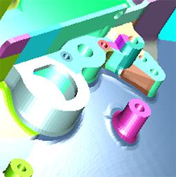
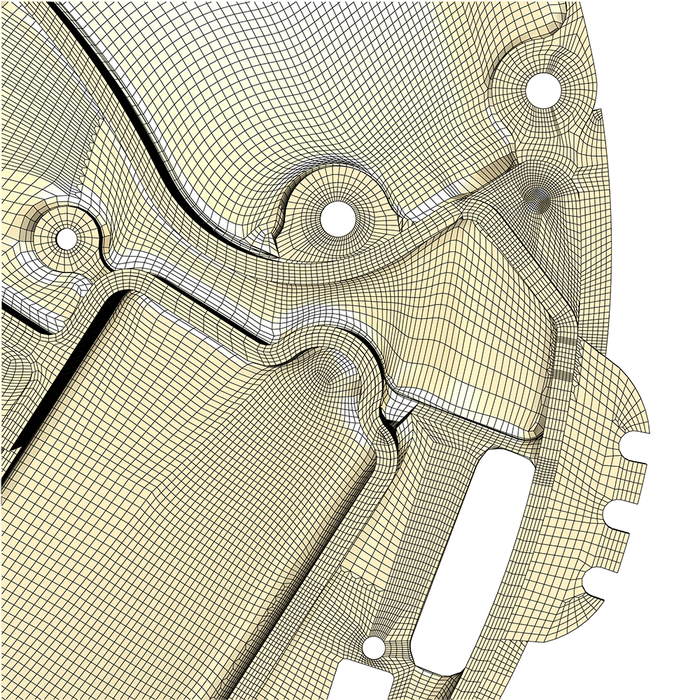
Assembling Many Parts
In this example a complex model is broken into 177 parts and glued together. Each color represents a different part.

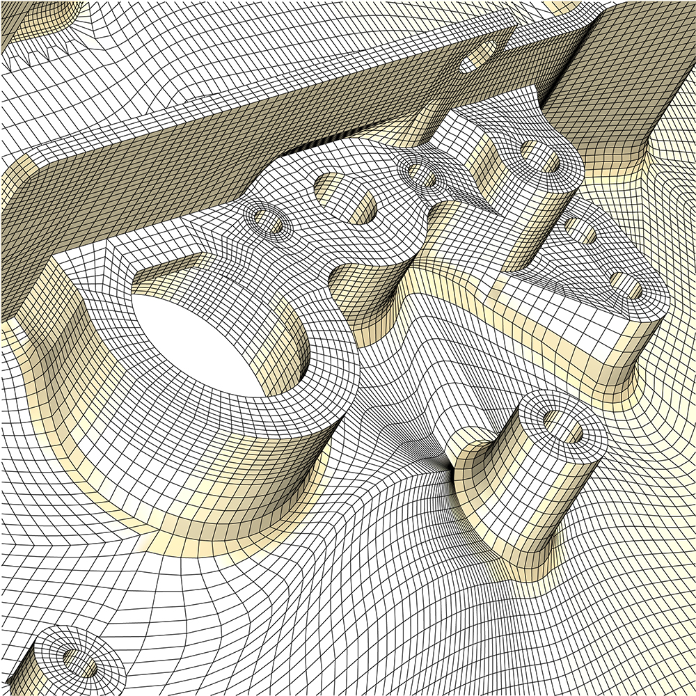
Zooming in on the mesh you can see the parts match perfectly
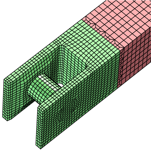
Transition Between Parts
If the number of elements in one region of a part is half or double the number in the other region on a part (possible the same part), then a transitional block boundary is needed. A row of hex (quad shell) elements at the interface are automatically replaced with a row that sews the two regions together to produce a node for node, edge for edge, and face for face matching across the interface.
 |
The transition layer can also sew together two parts where the number of elements differ in both directions along the interface. The ratio 2:4 or 1:3 is required in both directions. The ratios do not have to be the same in both directions. This example is 2:4 in two directions. |
For the complex model transitional elements are used at every level to match parts.
 |
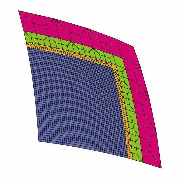
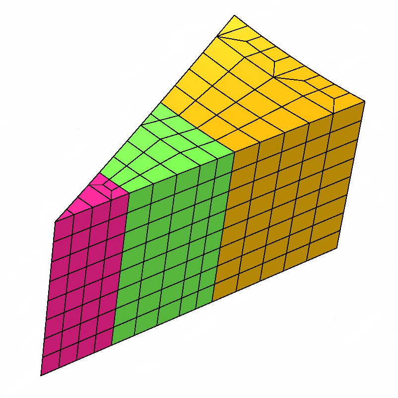
Multiple Layers Forming Locally Dense Meshs
Transitions can be layered to radically change the mesh density. The example below has three transitions in two directions with a transition scale factor of 12 in each direction.
 |
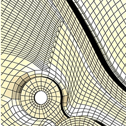
The same concept is seen for the complex model. A transition layer is used to increase the mesh density for a region.
 |
Irregular Region Filled using Transitions
Frequently, a part is needed that cannot be meshed with a simple block. If this part is in the interior where surrounding parts dictate the number of elements along the boundary of the part, a complex solution is needed. Several parts are constructed with transitions between them. If we do not have a difference of even number of elements one can force a degeneracy on a side by with a wedge element. Here is an example with three parts and three wedge columns. The wedges are easily formed by collapsing a face of a hex element.
 |
Use Transitions with Caution
All boundary conditions, initial conditions, and properties are maintained along when the trasitional element substitution is made. This feature can be abused because, by the very nature of these transitions, the quality is limited. In particular, the angles can be severe and can introduce numerical errors in the simulation. It is advised to carefully plan to reduce the number of transitions that are needed and to place these transitions in areas of low interest.